
FOR PREVIOUS TOPICS: CLICK HERE
Understanding UML: The Language of Software Engineering
Unified Modeling Language, abbreviated as UML, is a standardized notation used in software engineering to visually represent the structure, behavior, and interactions of software systems. Developed by Grady Booch, Ivar Jacobson, and James Rumbaugh in the mid-1990s, UML has since become the de facto standard for modeling software systems across industries.
Key Components of UML:
-
Diagrams:
UML comprises a set of graphical diagrams that represent different aspects of a software system.
-
Notations:
Each diagram in UML utilizes specific symbols, shapes, and relationships to convey information about the system being modeled.
-
Relationships:
UML diagrams depict various types of relationships between elements, such as associations, dependencies, and inheritances.
-
Abstraction:
UML promotes abstraction by allowing software engineers to focus on essential aspects of the system while hiding unnecessary details.
Exploring UML Diagrams: A Visual Journey through Software Modeling
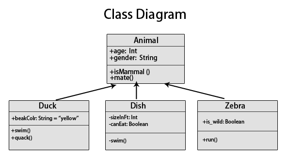
1. Class Diagram:
-
Purpose:
Represents the static structure of a system, including classes, attributes, operations, and their relationships.
-
Elements:
Classes, interfaces, associations, inheritance, and multiplicity.
-
Application:
Designing class hierarchies, defining relationships between classes, and modeling data structures.

2. Use Case Diagram:
-
Purpose:
Illustrates the interactions between system components and external actors.
-
Elements:
Actors, use cases, associations, and system boundaries.
-
Application:
Identifying system functionalities, capturing user requirements, and defining user-system interactions.

3. Sequence Diagram:
-
Purpose:
Represents the interactions between objects over time, emphasizing the sequence of messages exchanged.
-
Elements:
Lifelines, messages, activations, and object instances.
-
Application:
Modeling system behavior, capturing runtime scenarios, and analyzing system interactions.
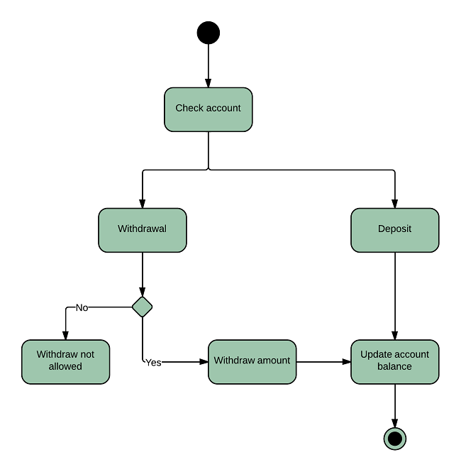
4. Activity Diagram:
-
Purpose:
Illustrates the flow of activities or workflows within a system.
-
Elements:
Actions, transitions, decisions, and control flows.
-
Application:
Modeling business processes, describing system behavior, and specifying control logic.
-
PPT FILE OF UML IN SOFTWARE ENGINEERING